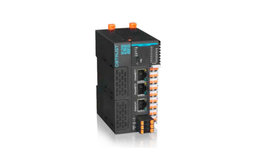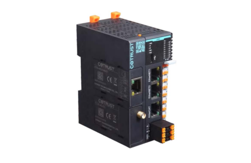
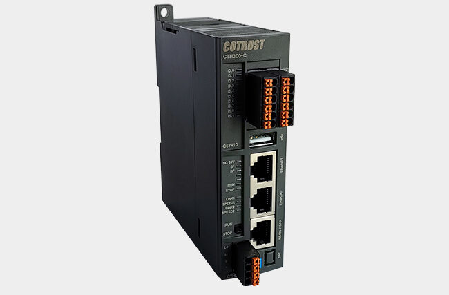
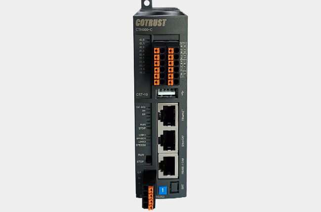
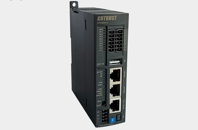
Controladores Estándar CPU CTH3-C57-A3
- Recomendado hasta 32 ejes EtherCAT
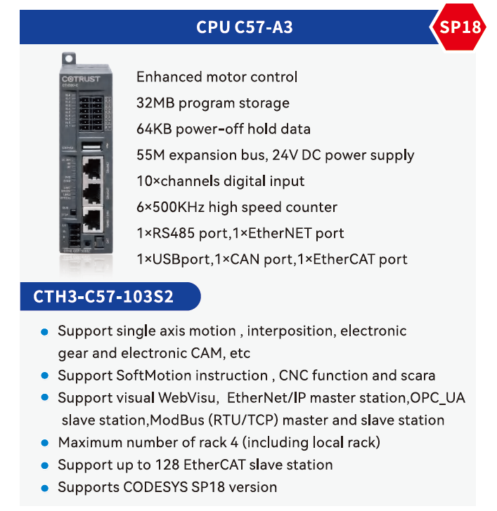
- Memoria de programa/datos 32 MB
- Memoria de datos remanente 64 KB
- Alimentación de 24 VDC
- 10DI, 6 contadores de alta velocidad frec. máx. 500 KHz
- 1 puerto RS485 (Modbus), 1 puerto EtherCAT, 1 puerto EtherNET, 1 puerto CAN, 1 puerto USB
- Conexión OPC UA
- Soporta Motion Control Axis (interpolación CNC, CAM electrónica y otras funciones de SoftMotion y CNC)
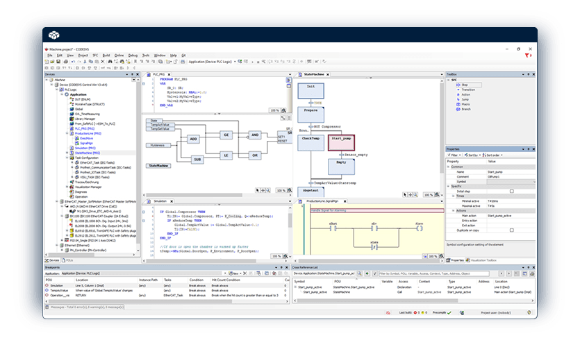
- Visualización CODESYS WebVisu
- Programación en entorno CODESYS 3.5
- Compatible con librería SP18
- Modelos: CTH3-C57 (32 ejes)

| Physical Features | ||||||||
| Dimension(W×H×D) | 34×115×100 mm | |||||||
| Power dissipation | 19.2W | |||||||
| Power Supply Features | ||||||||
| Rated input voltage | 24V DC | |||||||
| Input voltage rang | 20.4V~28.8V DC | |||||||
| Input current | 0.8A | |||||||
| Polarity reverse connection protection | Yes | |||||||
| Bus power supply voltage | +5V DC | |||||||
| Bus power supply current | 1.6A | |||||||
| LED Indicator Features | ||||||||
| 24V power indicator (green) | On: 24VDC power supply is normal; Off: No 24VDC power supply | |||||||
| SF indicator(red) | On: system failure; Off: no fault | |||||||
| BF indicator(red) | On: bus fault; Off: no fault | |||||||
| RUN indicator(green) | On:the system is running; Off: the system stops | |||||||
| STOP indicator(yellow) | On: the system stops; OFF = System running | |||||||
| Link1 indicator(green) | On: connection; Off: no connection | |||||||
| SPEED1 indicator(yellow) | On:100Mbps;Off:10Mbps | |||||||
| Link2 indicator(green) | On: connection; Off: no connection | |||||||
| SPEED2 indicator(yellow) | On:100Mbps;Off:10Mbps | |||||||
| I0.0~I1.1(green) | On: there is signal input; Off: no signal input | |||||||
| Instruction performance | ||||||||
| Bit instruction execution speed | 0.015µs/step | |||||||
| Floating-point instruction execution speed | 1.0µs/step | |||||||
| Memory | ||||||||
| User program memory | 32MB | |||||||
| Power down retention memory | 64KB | |||||||
| Integrated communication function | ||||||||
| Bus interface | provides extension module interface | |||||||
| USB port | provides USB main device interface | |||||||
| EtherNET port | 1*EtherNET port | |||||||
| RS485 port | 1*RS485 port | |||||||
| EtherCAT port | 1*EtherCAT port | |||||||
| CAN port | 1*CAN port | |||||||
| RS485 port | ||||||||
| Number of communication interfaces and protocols | 1*RS485 port (MODBUS_RTU free port protocol) | |||||||
| Free port baud rate | Baud rate 1.2Kbps~115.2Kbps,built-in Modbus master/slave function | |||||||
| PPI/MPI baud rate | 9.6Kbps,19.2Kbps,187.5Kbps | |||||||
| Maximum cable length per segment | Using isolation repeater: 1000m(115.2Kbps) | |||||||
| 1200m(38.4Kbps) | ||||||||
| No isolation repeater used: 50M | ||||||||
| Maximum number of stations | 32 for each segment and 126 for each network | |||||||
| Isolation | Communication port isolation | |||||||
| CANopen communication port | ||||||||
| Communication port | 1*CAN port | |||||||
| Maximum number of slave stations | 1 master station can be followed by a maximum of 32 slave stations | |||||||
| Protocol type | CANopen DS301 standard protocol | |||||||
| Support function | Supports automatic starting of CANopen Manager | |||||||
| Supports optional slave polling | ||||||||
| Support to start slave stations | ||||||||
| Support the NMT | ||||||||
| Support synchronous production | ||||||||
| Support synchronous consumption | ||||||||
| Support heartbeat generation | ||||||||
| Support activation time creation | ||||||||
| Transmission rate(kbit/s) | 1000 | 1000 | 800 | 500 | 250 | 125 | 50 | 20 |
| Maximum length (m) | 25 | 25 | 50 | 100 | 250 | 500 | 1000 | 2500 |
| Isolation | Communication port isolation | |||||||
| EtherNET port | ||||||||
| Communication port | 1*EtherNET port | |||||||
| Baud rate | 10/100Mbps adaptive | |||||||
| Protocol type | UDP_PPI protocol, support Ethernet programming and Ethernet communication between CPU | |||||||
| Maximum length of each cable | 100m connection directly | |||||||
| Maximum number of connections per site | UDP_PPI supports a maximum of 16 connections.TCP supports a maximum of 32 connections | |||||||
| Isolation | Communication port isolation | |||||||
| Ethernet network read and write instruction | Parameter | Type | Meaning | |||||||||||
| TCP_MBUS_MSG | EN | TCP_MBUS_MSG enabled | ||||||||||||
| First | BOOL | Read/write request bits. Each new read/write request must be use pulsed | ||||||||||||
| IP | STRING | Target IP address, Modbus over TCP fixed port 502 | ||||||||||||
| RW | BYTE | Operation commands :0– read,1– write | ||||||||||||
| Addr | DWORD |
Select the data type to read and write,0000 to 0XXXX — switch output 10000 to 1XXXX — switch quantity input 30000 to 3XXXX — analog input 40000 to 4XXXX — hold register |
||||||||||||
| Count | INT | The number of data (bits or words) that can be communicated. The maximum number of data that can be read/written by each MBUS_MSG instruction in the Modbus master station is 120 | ||||||||||||
| DataPtr | DWORD | Data pointer, if it is a read instruction, read back the data into the data area; if it is a write instruction, the data to be written is placed in this data area | ||||||||||||
| Done | BOOL | Complete bit, read/write function complete bit | ||||||||||||
| Error | BYTE |
The error code is only valid if the DONE bit is 1. The error code is as follows: 0 = no error 1 = Response validation error 2 = unused 3 = Receive timeout (no response from slave station) 4 = Request parameter error (slave address, Modbus address, count, RW) 5 = Modbus/ free port not enabled 6 = Modbus is busy with other requests 7 = Response error (response is not a requested operation) 8 = Response CRC checksum error 101 = Slave does not support requested functionality 102 = Slave does not support data addresses 103 = Slave does not support this data type 104 = Slave equipment failure 105 = The slave received the message, but the response was delayed 106 = Busy from the station, rejected the message 107 = The slave rejected the message 108 = Parity error in slave memory |
||||||||||||
| EtherCAT port | ||||||||
| Communication port | 1*EtherCAT port | |||||||
| Baud rate | 100Mbps adaptive | |||||||
| Protocol type | EtherCAT communication protocol | |||||||
| Maximum length of each cable | 100m connection directly | |||||||
| Maximum number of connections per site | Each master supports up to 128 EtherCAT slave stations | |||||||
| Support function | Support for distributed clock configuration, redundancy settings | |||||||
| Support startup parameter configuration | ||||||||
| Support for configuring PDO parameters and mappings | ||||||||
| Support for configuring bus cycle cycle, configuring startup check vendor ID and product ID | ||||||||
| Programming software | ||||||||
| Programming software package | CODESYS programming platform SP11 version. | |||||||
| Programming language | IEC61131-3 programming language: CFC/FBD/LD/IL/ST/SFC | |||||||
| Protection function | ||||||||
| Power supply protection | Power supply provides reverse connection protection function and surge absorption function | |||||||
| Interface protection | Communication port lightning protection | |||||||
| Local I/O expand capabilities | ||||||||
| Maximum number of racks | 4 | |||||||
| Maximum number of modules |
Main rack extensions: 11 (power module, CPU, relay module, 8 signal modules) slave rack extensions: 10 (power module, relay module, 8 signal modules) |
|||||||
| Remote I/O expansion capabilities | ||||||||
| CAN extends the maximum number of master stations | 1 | |||||||
| Maximum number of CAN slave stations | Each master station CAN connect up to 32 CAN slave stations (277C) | |||||||
| Maximum number of EtherCAT extended slave station | Connect up to 128 EtherCAT slave modules, each EtherCAT slave module has a maximum of 8 signal modules | |||||||
| Support motion control function | ||||||||
| C57-10 | Softmotion and CNC | |||||||
| Real time clock | ||||||||
| Power-down retention time | Power-down retention time is about 112 hours (typical value), and the power-down retention time can reach at least 1 year after connected with external battery | |||||||
| Accuracy | Less than 60 seconds per month | |||||||
| Digital input features | ||||||||
| Integrated IO | 10 | |||||||
| Input type | Leak/source | |||||||
| Rated voltage | 24V DC | |||||||
| Input voltage range | 20.4~28.8V DC | |||||||
| Surge voltage | 35V DC,last for 0.5s | |||||||
| Logic 1 signal (min.) | 15 VDC,2.5mA | |||||||
| Logic 0 signal (Max) | 5 VDC,1mA | |||||||
| Connect 2-wire proximity switch sensor (BERO) | 1mA(maximum allowable leakage current) | |||||||
| Input filtering | Support 0.2us,0.4us,0.8us,1.6us,3.2us,6.4us,12.8us、0.2ms,0.4ms,0.8ms,1.6ms,3.2ms,6.4ms,12.8ms,default is 6.4ms | |||||||
| Isolation (field and logic) | 500V AC,1min | |||||||
| Isolation group | See wiring diagram | |||||||
| Simultaneous connection input | 10 | |||||||
| Maximum cable length | 500m(standard input) | |||||||
| Shielded | 50m(high speed counter input) | |||||||
| Unshielded | 300m(standard input) | |||||||
| Pulse capture input | 10 | |||||||
| High speed counter | Total | 6 | ||||||
| Single phase | 6×500KHz | |||||||
| Two phase | 4×250KHz | |||||||

Descargas
CODESYS
Software WebVisu
También te puede interesar…